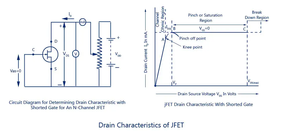

Therefore, depletion layers penetrate more deeply into the channel at points which are more closer to drain than the source. The gate is more negative to those points in the channel which are nearer to drain than the source. When a positive voltage is applied to the drain terminal with respect to source terminal without connecting the gate terminal to the supply, the electrons starts moving from source terminal to drain terminal whereas conventional drain current I d flows through the channel from Drain to the source.ĭue to this flow of current, the uniform voltage drop occurs across the channel resistance which reverse bias the diode. Similarly, if we reduce the negative voltage across the gate, the depletion layers start reducing causing decrease in resistance and increase in drain current I d. If we further increase the negative voltage across the gate, depletion layers meet at the center and the drain current cut off completely. With the increasing resistance and reducing current I d, the channel starts narrowing. The result is that the reverse bias at the drain end is more than that at the source end making the width of depletion layer more at the drain. When the drain current flows through the channel, there is a voltage drop along its length. When the gate is negative bias with respect to the source and drain is applied with a positive bias with respect to the source, the p-n junction got reverse biased and forms depletion region. Vgs= 0, the depletion region around the p-n junction are of equal thickness and symmetrical in nature. Vds = 0 nor any bias is applied to the gate terminal i.e. When neither any voltage is applied across source to drain terminal i.e. Jfet operates in three conditions depending upon the voltage applied across terminals:

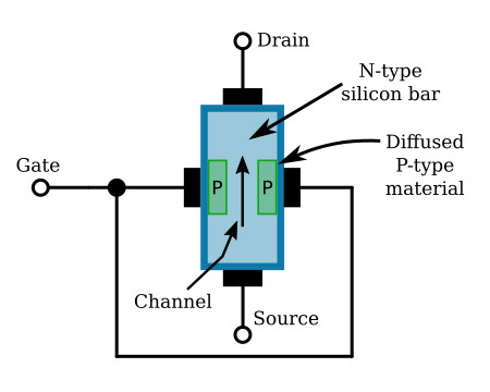
As shown in the figure above we explain how channel width change when we apply either a positive voltage or negative across it. The width of the channel varies in accordance with the magnitude of the bias applied to the gate terminal and source-drain terminal. Here we explain n-channel jfet operation because it is more preferable. electrons are majority carriers in n-channel and holes are majority carriers in p-channel. JFET Working Operationīoth N-channel JFET and p-channel JFET are operated in the same way, although the charge carriers are inverted i.e. These diodes are known as the gate -source diode and gate- drain diode. Gate-source forms one p-n junction diode while Drain forms another p-n junction diode. Gate terminal is used to control the flow of current from source to Drain. The p-n junction forms a terminal or gates internally known as a gate terminal.īy using battery it makes ohmic contacts at the two ends of the channel one is called source terminal and other is called Drain terminal. Similarly in p-channel JFET, smaller pieces of n-type silicon material diffused on the opposite sides of its middle part forming p- n junction and a p-type silicon bar considered as the channel. In an N-channel JFET, two smaller pieces of p-type silicon material diffused on the opposite sides of its middle part forming p- n junction and an n-type silicon bar considered as the channel.


 0 kommentar(er)
